en
In 2013, when I started writing these pages on dimensions of Lego parts, I thought it would be easy and quick.
After all, I had compelling evidence that the basic values were exactly 8.0mm and 9.6mm. My reason for going beyond that was making 3D models of parts so that I could document and animate some of my own constructions.
3D models do need to resemble the real thing sufficiently well, but the more important aspect, especially for 3D animation, is accurate relative positioning of parts. I needed to know much more than the 8.0mm and 9.6mm values, especially about gears and Technics stuff.
But as I went on, things did not converge. What I modelled in one session seemed to be contradicted by what I measured in another one. I needed a closer look.
Getting Lego part dimensions is not as simple as it looks.
Understanding Lego dimensions was an iterative process, and so is reading these pages: it is too difficult to give a simple linear narrative, you will have to accept some material at first, and come back to it later.
After many observations it turned out that there is no reproducible single set of measures. Over time the shapes, even of the classic bricks, evolved. A 1960s brick fits a 2010s brick, but it is not the same. There were also parts that should have shared a common measure but did not. And there was the difficulty of measuring accurately the features of very small parts.
Lego parts are made in very precise moulds but only certain relative positions are maintained with high accuracy. Separating the important dimensions from the unimportant ones took more time and thinking than I had imagined. But one guideline remains:
Guideline: all parts have to interoperate, independently of when or where they were made.
A set of measurements common to all parts, stable in time and space, does exist. But it is not that of the immediately visible features. Worse, in some cases older parts in fact do not interoperate with newer ones!
The purpose of these pages is to expose what I believe are the conceptual dimensions. There are only few of them. They may be difficult or impossible to observe directly. The other, more directly visible dimensions may not be too important. For example, the measured width of Technics beams and liftarms varies from 7.4mm to 7.8mm, but it is never in conflict with the dimensions of other parts.
I have limited the precision of conceptual dimensions to 0.1mm, but I am certain that the moulds are much more precise, I think the acceptable tolerances in their manufacture are close to those used by makers of quality watches.
This is the basic dimensions page, but there is also:
These pages do not discuss the many interesting qualities of the ABS plastic plastic.
Before we can go on, we must define what we are talking about. To avoid ambiguity, I use these terms:
So, model refers to a virtual 3D object in a computer program, while the word construction is reserved for an assembly of Lego parts.
Lego denotes the brand or concept, not a part; there is no plural “Legos”.
* actually there is always some friction, but very little of course.
Giving a list at this point is an a priori action: you have to accept it without yet knowing the reasons. It may also block your mind to different views on the matter. I hope not.
The table below may change over time. It is no good trying to understand it just now, please read the entire page first, and also the page “more dimensions”
Red highlighted designations are what I deem to be conceptual dimensions, i.e. you might say they are in some sense “fundamental”.
| Value (mm) | Designation | Type |
|---|---|---|
| 0.1 | horizontal play | measured |
| 0.1 | under-tube clearing | measured |
| 0.4 | fingernail ridge | measured |
| 0.8 | depth of bearing counterbore | measured |
| 1.6 | width of peg ring | measured |
| 1.8 | knob height | measured |
| 3.1 | diameter of under-stud | computed |
| 3.2 | plate thickness | exact |
| 4.8 | axle diameter | exact |
| 4.9 | knob diameter | measured & computed |
| 4.9 | under-tube inner diameter | measured |
| 4.9 | axle bearing diameter | measured & computed |
| 5.7 | height of front knob | measured & computed |
| 5.8 | height of bearing centre | measured & computed |
| 6.4137 | diameter of under-tube | computed |
| 6.2 | diameter of bearing counterbore | measured |
| 6.2 | effective bearing length | computed |
| 6.2 | effective peg length | computed |
| 6.2 | height of bearings on gear hubs | measured |
| 7.4 | width of special Technics beam | measured & computed |
| 7.4 | width of some Technics beams | measured |
| 7.5 | width of some Technics beams | measured |
| 7.6 | width of some Technics beams | measured |
| 7.8 | width of unit brick | measured & computed |
| 8.0 | horizontal pitch | exact |
| 9.6 | vertical pitch | exact |
| 15.6 | length of 2-unit axle | measured |
| angle of angled liftarms: 53.13…º | computed |
Already at this stage there are problems: a Technics beam must be less wide than 7.8mm, but there are at least three values used in production. Maybe there should be a red-highlighted designation width of Technics beam with a value 7.4<=…<=7.8 but that is perhaps going a bit far.
The table has only 9 important values; the other ones are derived from them, as are all measurements not in the table. For example: the 3.2 thickness of a plate is not marked as a conceptual dimension because it is just 1/3 of the vertical pitch of 9.6mm.
Thus the important conceptual dimensions must be independent of each other. One might however argue that the values of 9.6 and 3.2 were designed together: one had to fit a whole number of times into the other. Plates existed very early on, but I don't know if they were conceived at the same time as the classic bricks. If they were designed together, then very likely the trio of horizontal pitch, vertical pitch and plate thickness are really only two proportions (1.2 and 3) plus some choice of implementation length (8mm), and it could even be argued that there was some unconscious aesthetic preference for the ratio 1.2/3 so that in the end there were only two numbers: 1.2/3 and 8mm. Did the original designer ever reflect on this at the time?
The fewer independent numbers we have, the better. I propose that the axle bearing diameter is nothing else than the knob diameter (knobs do fit in bearings) which reduces the number from 9 to only 8.
An obvious choice is to make all numbers even, or multiples of 4: symmetry is then easier to deal with. That is not quite the case, since knobs are definitely 4.9mm across, not 4.8.
I am going to derive the basic dimensions of Lego bricks by observation and reasoning, trying to imagine what the Lego engineers did when they designed the system.
Instead of asking the engineers what they did, I am studying the objects they made; this is called reverse engineering.
Caveat: like anything I write about Lego, there is no guarantee that the Lego engineers actually reasoned in the way I outline here. It may well be that this page would make them roll on the floor laughing. I hope not.
Lego bricks are entirely metric. That means the design dimensions are round numbers when measured in the metric system.
At first approach there are two basic numbers.
The horizontal and vertical pitch are the first conceptual dimensions.
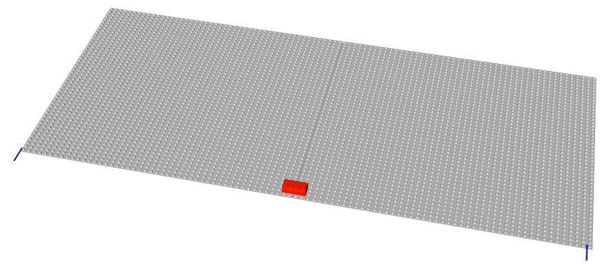
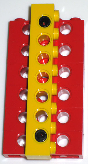
Do we know those are correct values? Yes, because they hold over large distances. In principle we could measure the distance between knobs by measuring from an edge of one knob to the same edge of the next one, as shown by the two horizontal blue lines:
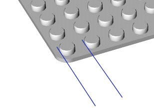
That is very difficult to do if we want a good value. It is much more accurate to measure between knobs that are far apart and then divide by the number of knobs.
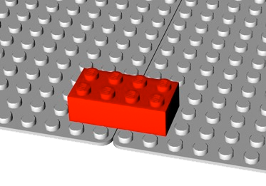
I took a 48×48 knob base plate, put two bricks on it as in the image, and measured 295.75mm ±0.25mm (the metal strip meter is divided with 0.5mm marks) for 37 horizontal steps( 1 , 2 ).
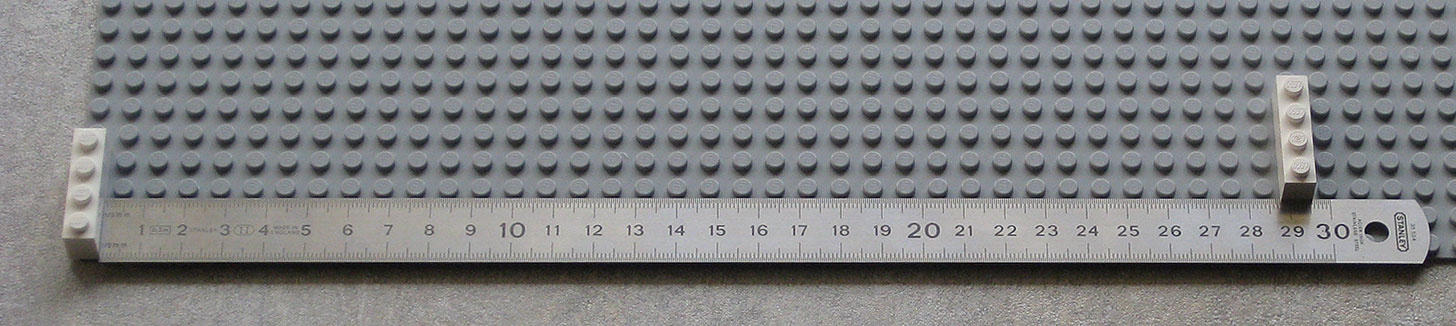
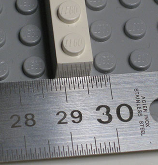
That gives 7.993mm ±0.007mm or 8mm to within better than one hundredth of a mm.
If you are tempted to measure over a distance wider than a base plate, you might think of putting several together, but in that case do not forget there is a gap necessary of 0.2mm (see below why) and so you must therefore link the plates by bricks so the distances between plates is rigourously kept:
In the rest of these pages the word “unit” is sometimes used for the 8mm distance between knobs.
For measuring the vertical pitch we can make a tower of, say, twenty bricks high, measure the height and divide by 20 to get a good value for the vertical pitch.
I measured 192.0mm ±0.25mm so that is 9.6mm ±0.013mm. Be sure to line up the meter correctly at one end and to look vertically down at the other end to avoid parallax errors (e.g. the angle of the photo might lead you to think I should have measured slightly less than 192mm).
Note these important aspects:
Consider this coordinate system:
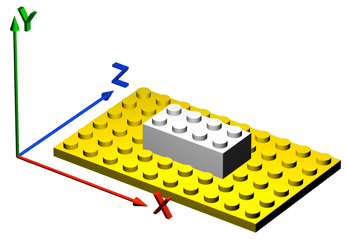
In the horizontal plane, along the X and Z axes, the distance unit is the same (8mm), but along the vertical, y-axis, it is different. Lego does not “feel” the same horizontally as vertically. It is anisotropic. It is also highly oriented, as mostly knobs are pointing in the vertical direction, at least in most static constructions. Among AFOLs there is a special name, "SNOT" or "Studs Not On Top", for constructions where most knobs do not point upwards, showing that the anisotropy does play an important role.
There may be an underlying smaller pitch: 0.8mm. That goes 10 times in the horizontal pitch and 12 times in the vertical pitch.
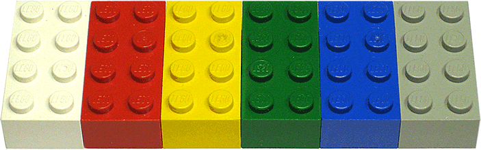
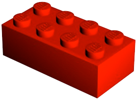
The design dimensions of the classic brick with two rows of four knobs are then 16mm×32mm×9.6mm. It seems that making the brick only 8mm high did not look nice, it’s too “flat”, whereas making it 12mm high (one and a half times the pitch) looks too “thick”.
The value of 9.6mm is also supported by the Technics bracing methods:
9.6×5=8×6=48 and this bracing method also holds over large distances.
Therefore there is no doubt that the basic pitches have exact design values of 8mm and 9.6mm.
(1) It is important to measure from the right hand side of the brick at the left to the right hand side of the brick at the right and not between the bricks, since it is not guaranteed that bricks have a width exactly equal to the horizontal pitch. In fact they don’t: they are 0.2mm less wide.
(2) The measurement should be done at room temperature, as the expansion coefficient of the plastic and the strip meter are not the same. Stainless steel is produced in several varieties, with expansion coefficients ranging from 9.9 to 17.3×10⁻⁶/K at 20ºC (possibly the smaller value for stainless steel used in measuring instruments). For the plastic acrylonitrile butadiene styrene (ABS) of which Lego bricks are made it is 73.8×10⁻⁶/K so at least 4.3 times more than for the ruler, but still quite negligible. A normal base plate is about 380mm wide and by warming up from 15ºC to 25ºC it would expand by less than 0.3mm.
Making the real bricks exact multiples of 8mm long has an unfortunate side effect: the faces of adjacent bricks touch. That is not a good idea unless you are never going to move them again. To avoid the faces rubbing against each other while building or dismantling, a small gap is introduced. I am much less adamant about the exact value of this gap than I am about the value of the basic pitches, but my measurements have consistently turned up the value of 0.1mm play on each side.( 1 )
Leaving 0.1mm on each side then makes the basic 2x4 brick 32mm-0.1mm-0.1mm = 31.8mm long and 16mm-0.1mm-0.1mm = 15.8mm wide and 9.6mm high. When a brick is measured, the play on each side is subtracted and the brick thus seems shorter by twice this play: 0.2mm less than would be expected.
Carefully note that there is now a gap of 0.2mm (twice the play) between adjacent bricks horizontally:
You can also use a set of gap/thickness blades like these:
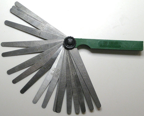
You may find that a 0.2mm blade sticks between bricks when they are placed on top of others, this is partially due to the knobs of the underlying bricks forcing the walls of those on top slightly outward, which causes the friction necessary to hold the construction together. It does not occur between bricks that are held only at the top.
Note also carefully (and think about it hard if necessary!) that these actual dimensions of a brick do not allow them to be put horizontally in other places than exact multiples of 8mm!
The 31.8mm brick is definitely not a uniformly scaled down version of the “ideal” 32mm brick! It is really a 32mm brick from which 0.1mm has been shaved off on all vertical sides to ensure a reasonable gap.
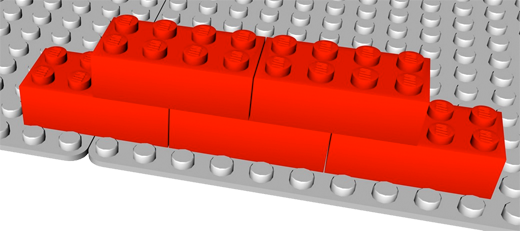
To illustrate why this also works in all combinations, consider this top view of a yellow plate with some red bricks on it:
There is no need for play in the vertical dimension, indeed it is not desirable at all.
Working hypothesis: the play value of 0.1mm is a conceptual, recurring dimension.
The 0.1mm play is the third conceptual dimension, and it is measured.
(1) Measuring the lengths of 1×n bricks was an interesting endeavour as it turned out that the longer the brick the more play there seemed to be! This is probably due to the fabrication process: as bricks are injection-moulded relatively hot, they contract on cooling down. Longer bricks will contract relatively more than shorter ones. I measured a large number of bricks of lengths 1,2,3,4,6 and 8 knobs. The average double play (gap) is shown by the red crosses and the blue trend line in the graph below:
The dotted green horizontal line is my hypothesis of a gap of 0.2mm. The graph shows that this hypothesis holds well around sizes 3 to 4 knobs, which is what most bricks are.
Another way to measure the play in an indirect fashion is to construct a long wall and bend it:
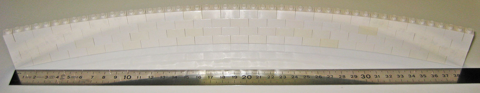
Bending can occur only to the amount the bricks can rotate to close the play gap. I chose 1×2 bricks for a wall of 25 bricks.
Measure the chord 2a and the sagitta (arrow) b as indicated in the drawing on the left. I found a=387/2=193.5mm and b=33.5mm. A little trigonometry gives the values of the radius R and the angle α: a=Rsinα and b=R-Rcosα; solving those equations I found R=575.59mm and α=0.3428547 (both values of course given here with far too high precision, but it's what my spreadsheet returned).
Now let's look at the drawing on the right, in which the red rectangle represents (not to scale) a single 1×2 brick. Since 2α represents 25 bricks, γ is α/25. If we call the value of the play p, then PQ is 8mm - p, and it is also Rsinγ, so p=8-Rsinγ. I found p=0.1065mm.
This is an easy one. We are discussing the arm with sides of 3 and 5 holes joined at a hole, I will call that the 3-1-5 form. Put the liftarm on an imaginary grid of bearings, pitch 8.0mm in both directions. The long side is 5×8.0mm long and its axle gripping hole at the end lines up perfectly with one of the bearings.
That makes a right-angled triangle of sides 3, 4 and 5: the simplest one with integer values for all sides.
Therefore the value of the angle in the figure below is atan(4/3)=53.13…º .
There are three common types of angled liftarms: 90º angle, 45º angles and 53.13…º angle
In the figure below the legend on the left of each liftarm gives the distance to the angle corner in red and the angle in green. The double-angled liftarm has a middle segment corresponding to 2×√2=2.828427… units.
Strictly speaking the 4-90-2 part is a beam, not a liftarm because it cannot grip an axle.
The figure also leaves out the thin versions, some of which have 120º angles.
When one plans to create some object, one usually starts with very simple and rough sketches. When the time comes to make the thing from physical stuff, one usually runs into a few minor problems: a bolt may be in a place where it is difficult to put a nut on, a piece of wood may be too thin for the job. These minor problems are easily solved, and if the contraption happens to be so useful that it can be turned into a sellable product, then maybe a complete re-think is necessary to make production and/or usage easy.
Toys do not escape this process. If you have to explain the building of a model house with classic Lego bricks to someone who has never seen a piece of Lego, you may talk about rectangular plastic blocks with knobs that fit tightly into holes at the bottom of bricks you put on top. You may also usefully mention that they are 32mm by 16mm by 9.6mm because those are their conceptual dimensions.
But as we saw, actual Lego bricks are much more sophisticated than this first approximation. There must be a slight gap between adjacent bricks or it would be very hard to put them in a line (and you would soon scratch the sides too); the knobs must be very slightly larger than the holes they fit in or they would not stick sufficiently well; the plastic must give a little but not too much, and so on.
We may therefore describe the Lego bricks in terms of their conceptual or design dimensions, which are different from their actual or production dimensions.
The design dimensions of the basic brick are 16mm×32mm×9.6mm but the actual bricks are produced as 15.8mm×31.8mm×9.6mm. To think about bricks and constructions built with them you should use the conceptual dimensions or you will go crazy. To produce bricks (which you will be unlikely to do unless you have an extremely good 3D printer) you should heed the reasons for the production dimensions.
There are also side-effects of production. One is that the very slightly lower pitch values than 8.0 and 9.6 are probably due to the cooling, though cooling from the 230ºC moulding temperature down to room temperature should contract the parts much more than the negligible difference. A more visible effect are the “dimples” in the sides of some parts caused by cooling contraction.
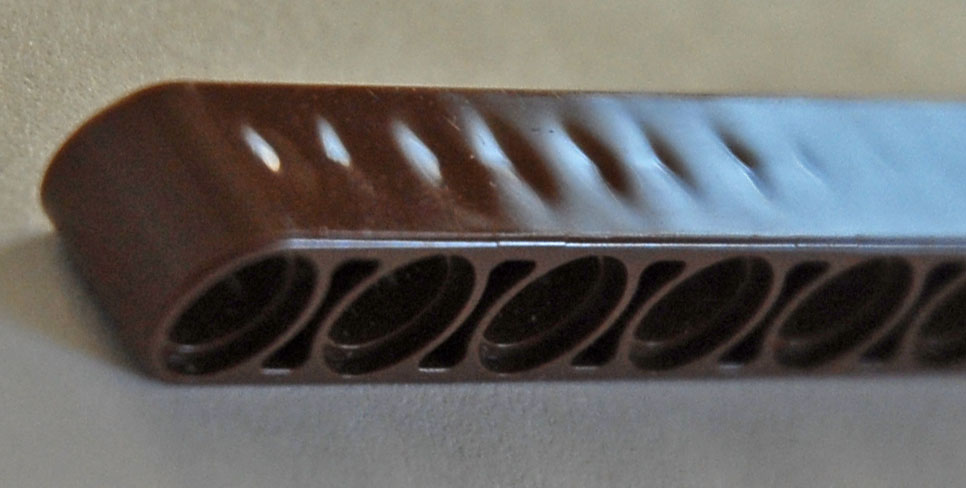
These dimples are not important since the sides of beams are not normally exposed in aesthetically important places. But from their existence I conclude that the cooling of these beams takes place first around the axle holes, as those must be, and are, very precise. The fact that in the process some plastic then gets “sucked in”, leaving the dimples, is acceptable. Various other parts show similar dimples but in all cases the important surfaces have the correct dimensions.
In all other pages I will mention brick sizes in the conceptual dimensions and not the actual production dimensions. The small differences between the two always have to do with achieving sufficient play or sufficient friction, but never with positioning the bricks with respect to each other.
The status of the 0.1mm play value is a bit ambiguous: is it really a conceptual value, as I think it is, or is it just a production thing, that can vary wildly? It has to be there, but it is not terribly important that it always has exactly the same value. One could say that its existence is conceptual but its actual value is not too important as long as it is within tolerances. On the other hand, it shows up in many places, not just in classic bricks.
Going from small to large, our perception demands geometric progression. This is also the most useful in engineering.
For example, adding a row of knobs to a 2×1 brick to make it a 2×2 brick will double its size, but adding the same row of two knobs to a brick that is already 2×10 will not seem to be of much use, the resulting brick is proportionally not much bigger than the original one.
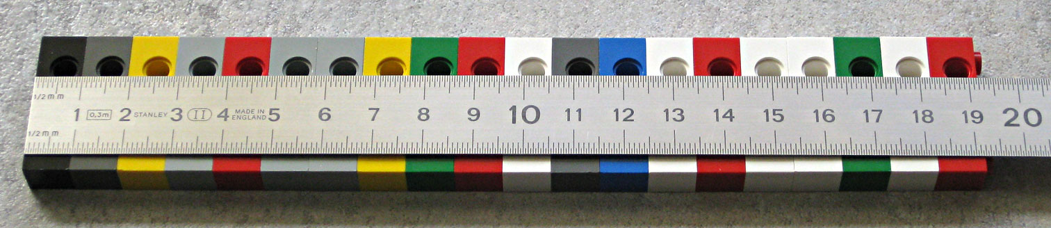
Lego axles in the earlier days were produced in lengths that were multiples of 2: 2, 4, 6, 8, 10 and 12. That is a linear sequence.
There were two awkward aspects: at the low end there was too big a difference between 2 and 4, with length 3 missing but often useful; agt the high end there were no really long axles. In the figure below the black lengths represent the early axles (and they were all black indeed); the grey lengths were added later and filled the gaps at the low end. There is no length 9 because that is not useful. The white lengths are the very long axles introduced even later; there are quite big gaps: 4 units from 12 to 16 and 16 units from 16 to 32. But the sequence now approaches a geometric progression better:
The 32-unit long axle really is an outlier, it makes sense only if there were one or two more axles with lengths between 16 and 32. In sets it is often used as a pole, not an axle to carry wheels or gears.
Reasonable constructions rarely need axles longer than 16, that is why I limited the fit of the red exponential curve to the set from 2 to 16.
Positions of bricks are almost always constrained by having to fit to an imaginary grid with spacing of 8mm horizontally and 9.6mm vertically.
To my knowledge that constraint can only be circumvented in three ways:
The grid constraint is a severe one for some constructions and it is at the origin of many ingenious applications of connectors.
The difference between the 8mm horizontal pitch and the 9.6mm vertical pitch is also at times frustrating when building technical structures.
Finally, don’t forget there is more about Lego brick dimensions: