Project Goal
This page tells how to make a video of an animated model of a Huygens type maintaining power mechanism for a weight driven pendulum clock.
This is the result:
en
This page tells how to make a video of an animated model of a Huygens type maintaining power mechanism for a weight driven pendulum clock.
This is the result:
While winding up the weight of a simple weight driven pendulum clock, the force of the weight on the going train is removed. The clock will not tick during this period. For a regulator clock this is unacceptable: power to the going train must be maintained while winding.
Huygens solved this problem by using a chain drive with a closed chain. In the schematic diagram shown below, the chain goes over the clock's driving or big wheel, is pulled down by the weight hanging from the weight pinion, but is rewound by a winding wheel which "recycles" the used chain length back to the big wheel. The winding wheel is kept from rotating the wrong way by a ratchet and pawl, fixed to it.
In the diagram five wheels are shown:
We use the above abbreviated wheel names throughout the rest of this page.
For each wheel the chain makes contact at the left or right side, goes around half of the wheel, then separates from it on the other side.
For each wheel a fixed number of links is always in contact with the wheel, covering half of its circumference, hence the number is half the number of teeth of the wheel.
Most of the time the winding wheel WW is stationary because it cannot rotate backwards. To avoid entaglement of the loose chain segment, that segment is kept taut by a small tension weight hanging from tension pinion TP which has no other function.
As the clock "unwinds" the driving weight descends and the tension pinion moves upwards. When the driving weight has reached its lowest point (and the tension pinion is high up) the clock must be wound: the winding wheel is turned counter-clockwise which hauls the weight up again (and the tension weight goes down). During this rewinding the driving weight force is not removed from the big wheel (in fact it increases slightly).
Making a simple 3D model of this mechanism is not difficult, but animating it poses a few problems:
Use Cinema 4D (C4D) as the animation program.
The rest of this page will use terms from C4D's vocabulary. You can download a copy of the C4D file.
Control all motion with C4D's xpresso formulae.
Make a spline for the chain path; this is a sequence of Bézier curves.
Animate the chain spline by using point-level animation, moving the spline points with xpresso.
Use a cloner object to duplicate the link clones along the chain spline, by combining the spline and the cloner with a spline effector.
Moving the link clones along the spline is done by changing the offset of the spline effector of the cloner object.
Take the length unit to be 1, with no real measurement unit attached.
Take the chain link length LL as fundamental.
If all chain spline segments between wheels are vertical and straight then the sum of the diameters of the pinions and the winding wheel must equal the diameter of the big wheel. Postulating the same tooth pitch for all wheels, and adopting realistic numbers for the teeth, use 16 for the WP and TP pinions, 32 for the winding wheel WW and 64 for the big wheel BW.
Fix LL so that the wheel diameters are round numbers. With the above wheel teeth numbers the link length value of 3.926991 gives pitch radii of 40, 20 and 10 respectively.
Fix the number of links at 150, this fixes the chain length at
150×3.926991 = 589.04865.
Put the winding wheel WW at the origin.
Fix the height of the big wheel BW at 80 and the initial height of the weight pinion WP at −20.
Fix the frame rate at 30fps.
Fix a tick as one second. During a tick let the big wheel rotate enough to make the chain move over half a link length.
The heights of the weight and tension pinions are then determined by:
The problem is determining the shape of the chain spline as a function of time. The curved parts are arcs of a circle, therefore we know the size of the handles: 0.415×R where R is the circle radius. This is a property of C4D as mathematically for Bézier curves the proportion is 0.55228475×R.
Handle points cannot be programmed using xpresso.
Number the points of the spline starting from the top of the big wheel (see above diagram), moving around the spline clockwise:
Points 0, 1, 11, 5, 6, 7 do not move. The other points have fixed X-coordinates but move in Y.
The sum of the tension pinion height and the weight pinion height is constant:
distance(point 4 to 7) + distance(point 7 to 8) = K
The chain spline handles are: 16.60 8.30 4.15 (radii times 0.415).
A spline effector offset goes from 0% to 100% of the spline length. If there are n links then the percentage corresponding to one link is 100/n
xpresso must feed radians to the rotation angles of object, but in the Attribute Manager rotation angles are given in degrees.
Chain links are connected by pins (small axles) around which the links can turn relative to each other. These pins will engage with a toothed wheel by lying between two teeth. The centres of the pins are all equidistant: that defines the link length. The centres define the vertices of a polygon.
The C4D cloner object distributes links by measuring along the curve of a spline, not a polygon. But since the distance between two link pins is along a straight line, the links will appear slightly too close together along a curved segment of a spline than along a straight one. It does not help to make the radius of curved spline segments larger: an arc will always be larger than its chord.
Assume that even for the smallest wheel the difference between the length measured along the arc of a spline and along the chord is visually unimportant: even for the pinions the chord is 99.36% of the arc (note: for a square in a circle the side of the square is already 90.03% of the corresponding arc).
In all the following we must measure lengths along the curve.
The spline for the chain (see blue line in the diagram above) is composed of four straight segments joined by four half circles, one for each of the four wheels over which the chain runs.
It is didactically useful to make the video loop indefinitely. If the animation takes F frames, numbered 0 to F-1, then frame F, which is not part of the animation, must be identical to frame 0.
If a tick occurs every second, then at frame rate 30fps frames 0-29 show the first configuration, 30-59 the second one, 60-89 the third etc.
The clock keeps ticking while being rewound, therefore problem requires a whole number of teeth to be moved for all wheels.
Because BW moves over half a tooth at each tick, a looping animation must last an even number of seconds 2m. The number of frames to render is 30x2m.
WW must always rewind exactly what BW gave out, and because its radius is half that of BW, it must always rewind by turning over twice the angle that BW does.
At each tick BW rotates by 2π/64/2, WP and TP by 2π/16/4 and WW by 0 except when it rewinds.
If BW has an even number of spokes then a half turn is fine for looping, leading to a whole turn for WW. A half turn is 32 links, the length of the animation is then 64 seconds total. 30×64=1920 frames or frame 0 to 1919 and 2m=64 ⇒ m=32.
It does not matter when rewinding starts but it must stop when the configuration is that of one frame before frame 0.
Let 4 seconds be used to animate rewinding. During that time BW moves 2 links, therefore the WP drops by 1 link length because of that.
The animation goes for 2t=60=2×30 seconds before rewinding starts. WP has dropped by t/2=30/2=15 times LL.
Rewinding must move t+2 links to bring WP up to its original level, but 2m=2t+4 or m=t+2. No surprise really.
The ratchet wheel must start and stop at an angle with the pawl engaged, meaning it can only turn over a whole number of ratchet teeth, but that is guaranteed by the looping requirement.
WW must then turn over m teeth or m×360/32 degrees.
Rewind takes place over 4 seconds or 4×30=120 frames. The speed of rotation of WW is then 360/120=3 degrees per frame. But in those 120 frames the pawl has to go up and down a whole number of times. The number of teeth of RW therefore has to divide 120 evenly. Choose 30, which is close to the 32 of WW. A pawl up-down movement then lasts 4 frames. We use 3 to move up and one to move down again.
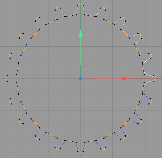
First create the chain link. Real chains are most often made from two different types of link: one with flanges inside and one with flanges that overlap the first ones. These two types then alternate along the chain. But that is rather complex to do here since it means creating two interweaving cloners with two spline effectors on the same spline. There are also chains made from only one type of link, where the flanges are bent. They are presumably somewhat less strong when used in motorbikes but for a clock this is not an issue. Here is the chain link used and three copies to show how they assemble:
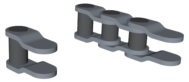
There is no need to model the holes in the flanges, especially not since the distance between links is not always exaclty the same.
By the way, the model is entirely made from primitive objects, there are no meshed forms. The only elements with point-level modelling are the splines for the chains and the splines for the gear wheel teeth.
Create the spline for the chain: use the spline drawing tool to make a spline with four straight and four curved segments. Use the structure manager to set the points at exact positions:
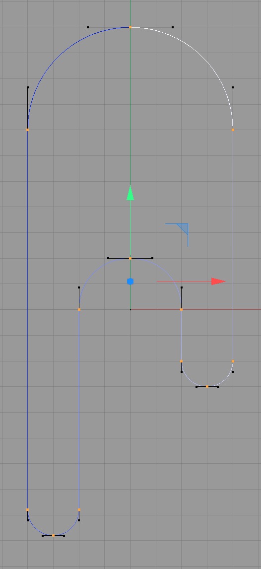
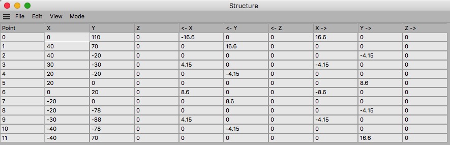
Note that the values for the curve handles are 0.415×R where R is the radius of the wheels, which gives 16.6 for BW, 8.6 for WW and 4.15 for the pinions.
Create a cloner for the chain links
Select the cloner, use the Mograph menu, Effector submenu, to create a spline effector, which will be added to the cloner.
Set the effector's spline to the chain spline
Add the chain link to the cloner. Set the Fix Clone to off, otherwise it's the cloner that decides the orientation and location of the object. In the attributes of the link (NOT those of the cloner!) use the coordinates pane to turn the chain link if it is not aligned to the spline in the desired way.
There are now three separate objects making the chain: the spline that is the chain path and is assigned to the effector, the spline effector, and the cloner which contains the chain link.
To make the chain links move along the spline: set the offset of the spline effector. The offset goes from 0% (first point of spline) to 100% (last point). We will do this with xpresso, as a function of time. In xpresso the offset value goes from 0 to 1, not 0% to 100%.
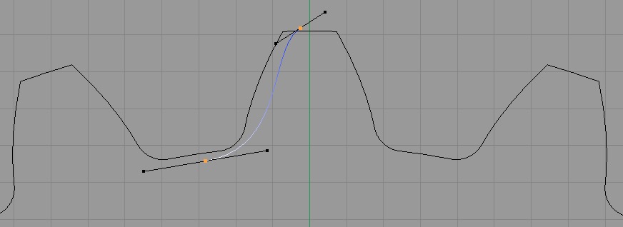
The four gear wheels can be created from C4D's built-in cogwheels. However, a chain runs over wheels with teeth which have shapes different from those available. The teeth should resemble those of bicycle gear wheels. Without going into the details, the choice is between using the built-in cog, setting the teeth parameters so as to resemble a bicycle gear as close as possible, or by designing your own gear.
I use a spreadsheet to design gears with arbitrary tooth shapes. You can download the spreadsheet for LibreOffice and Numbers if you want.
In short, I do these steps:
Step :
Step :
The spline thus obtained is of course no longer a primitive object like the cogwheel is.
I obtained the inlays by making them with C4D's built-in gear inlay parameters for a cog, converting the cog to splines, cutting the inlay parts out and then connecting them to the spline giving the bicycle teeth.
The pawl is an extruded hand-designed spline. The ratchet can again be made either with C4D's cogwheel or by the spreadsheet.
There is no point in detailing how to model one of the weights with C4D: just a cylinder and a sweep of a circle along a spline to form the hook.
As mentioned earlier, the centres of the link pins of the chain define the vertices of a polygon. Computing the motion of the points of this polygon using xpresso is very difficult. We approximate with a spline along which we clone links, even if this puts the links along the curved sections slightly too close together.
There are several additional C4D settings applicable per spline segment, but they don't really do what would be needed to get a polygon.
Assume that even for the smallest wheel the difference between the length along the arc and along the chord is unimportant visually, as it seems to be in practice.
Originally the idea was to animate the chain by increasing the spline effector offset. But this cannot be done by increments the size of the link length since the offset is measured along the curve: they must be increments of the arc length not the chord length, and when the starting point reaches the end of a curved segment it must change to the link length along a straight section. Then when it reaches the WP half circle, it must change to the arc length along that smaller circle, etc.
To avoid this complexity it is easier to "rewind" the chain by one link at each even numbered tick. This forward-backward movement is not distinghuishable from a continuous forward movement.
The xpresso program is rather large, somewhat tedious to build, but not really very complex:
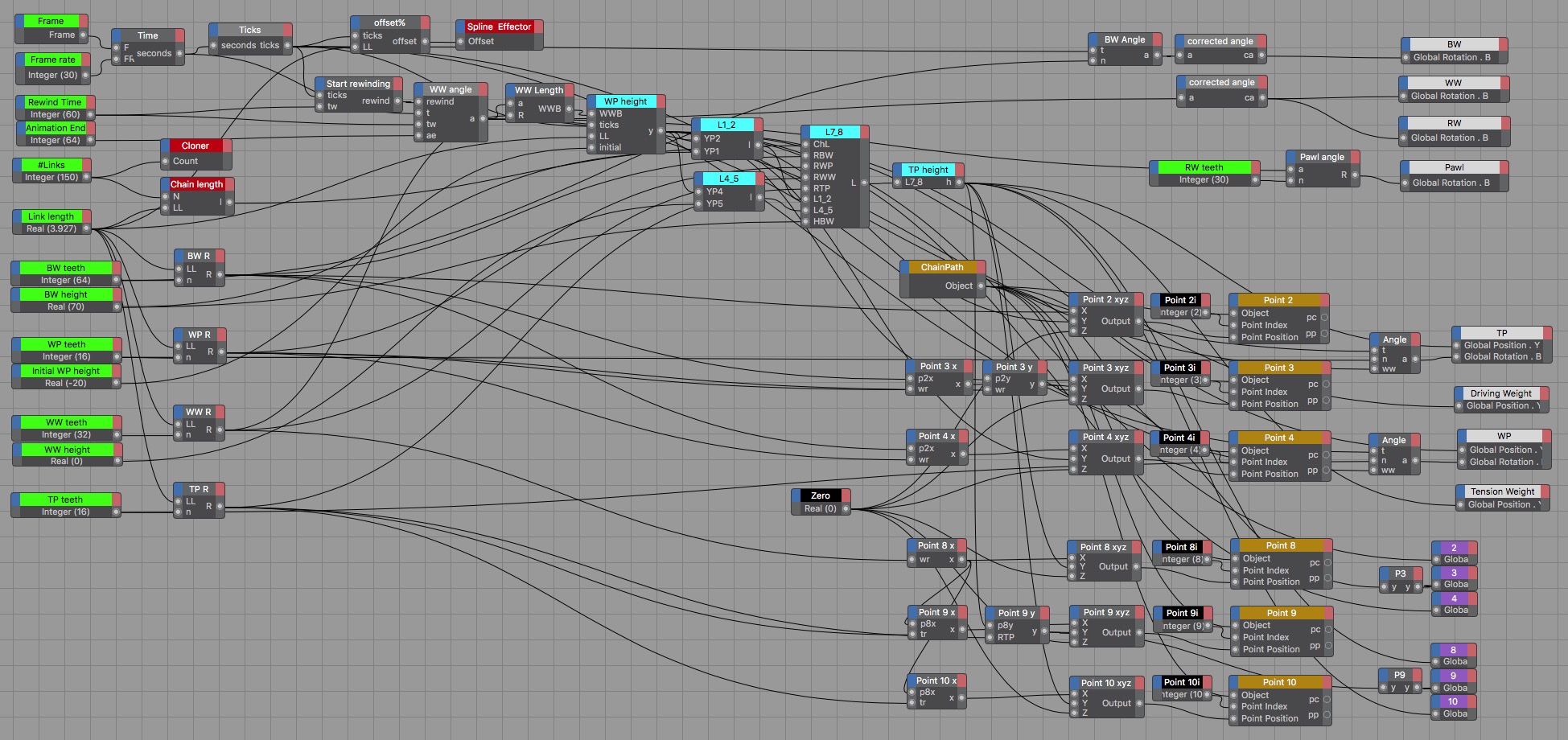
That is a large image taken from C4D's xpresso editor. I tried to develop the logic from left to right.
Start with the nodes at the left, with bright green titles. From top to bottom, they give the basic values:
The number of teeth of the ratchet wheel RW is also a basic parameter but is given more to the right in the picture.
There are three nodes with bright red titles: they correspond to the cloner object, the spline effector and the chain length. The chain length is of course not an existing object. Other objects present have nodes with coloured titles:
Some important values have nodes with bright cyan titles: the lengths of the chain spline's straight segments and the computed heights of the pinions.
There are a few integer values that are not parameters: the zero, given to the distance in the z-axis, the point numbers 2, 3, 4, 8, 9, 10 of the six moving points of the chain spline; their titles are black.
From the frame number and the frame rate we compute the time in seconds. This is a real number, the ticks is an integer which is the truncated value of the time.
The spline effector's offset will zero on even ticks and half a link on odd ticks, since we decided that we will create the motion effect by moving the chain back and forth along the spline. For some mysterious reason the required offset is 1%, whereas half of one of the 150 links represents 1/(150×2)= 0.333…% of the chain spline, the expected value.
The "Start rewinding" node outputs 0 as long as the ticks is less than the rewinding time of 60 seconds and is 1 after that. The rotation of the WW wheel must get to 360º between the rewinding time and the animation end time.
The WP height starts at the initial height, then the WP descends each tick, but is lifted proportionally to the angle of the WW. From that height also derive the lengths of the straight sections 1-2 and 4-5 of the chain spline. Those in turn give the length of the straight section 7-8, where the radii of the wheels and the height of BW play a role.
Finally we get the height of the tension pinion TP from the previous results.
The next thing to do is to set the moving points of the chain spline. All these points are at zero in the z-axis, hence the zero constant node. The x-values are also constants but we do calculate them from the values of the wheel diameters. The y-values are linked: there is one base value for the points 2, 3, 4 and another one for the points 8, 9, 10. The difference between points in a group is just the radius of the pinion.
C4D then needs a vector [x,y,z] to set the point position, which explains the presence of the column of nodes labelled "Point n xyz". Finally these values are fed into the point objects. Note taht C4D does not allow point-level animation by default, it has to be switched on in the animation toolbar.
The only thing left now is more ore less eye-candy: make the wheels rotate, link the weight heights to those of the wheels, and animate the pawl. That is straightforward except for the pawl: we decide to make the pawl angle a function of the ratchet wheel angle, using modulo arithmetic so that it starts its movement over again at the passing of each ratchet tooth. That is perhaps the least obvious formula:
mod( round(abs(a*180/pi)) ; (360/n) ) *1*pi/180
None of this is rocket science, but also most of it is not obvious, and I thank the Maxon/C4D staff for pointing out the value of point-level animation, without which it would not be possible to modify the chain's path.