This is the second page on Lego brick dimensions.
A Way to Determine Dimensions
Lego parts are fundamentally made to fit together: dimensions can be derived reasoning on simple constructions.
After determining the basic dimensions and the Lego “grid” of 8mm×9.6mm we need to find these measures:
- the height and diameter of the knobs
- the diameters of certain cylindrical features
- the diameter and placement of the axle holes in Technics beams
- the dimensions of Technics gears
We observe how certain pieces fit with other pieces, so that we can deduce within which limits the values of some of these measures have to lie. This method is of course no guarantee that the design dimensions really are that way, but for making 3D models it is largely sufficient.
Knobs
We start from the fact that the horizontal design spacing of knobs is exacty 8mm.
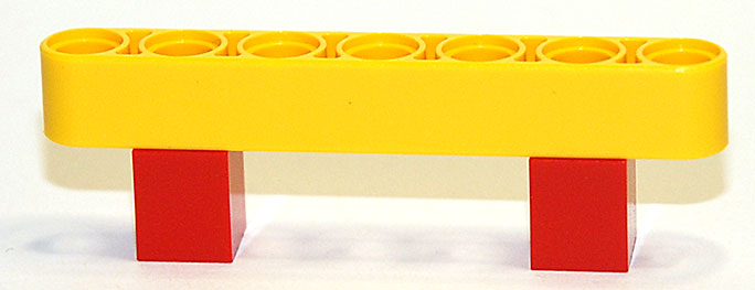
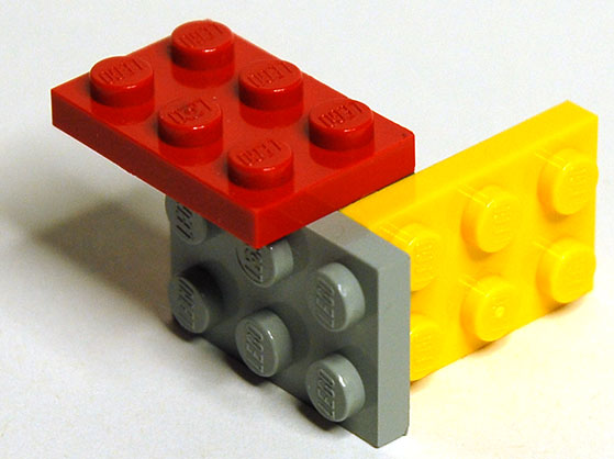
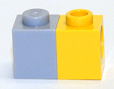
We observe this assembly:
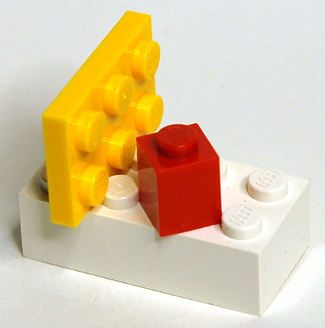
If you place the 1×1 brick carefully at 45º you will still see light pass between its vertical edges and the sides of the adjacent knobs. The diagonal of the brick is very slightly smaller than the gap between knobs.
But the “illegal” yellow plate is firmly stuck between two rows of knobs. “Illegal” means that the construction is not “according to the books” which is of course open to interpretation. You are not supposed to wedge plates between knobs. It’s “not done”.
Now because we can “brace” Technics bricks with pins, as was stated in the basic dimensions page, we know that the design height of the plate is exactly 3.2mm, and since it sticks between the knobs, the gap between knobs must be slightly less than 3.2mm. From this we can conclude that the diameter of the knobs must lie between 4.8mm and 4.9mm. Let us first exlore the hypothesis that it is 4.8mm, and the 1×1 brick is 8.0mm wide. In the two drawings below the stroke of the shapes is inside, i.e. the dimensions given include the thickness of the lines.
The edges of the 8.0mm brick clearly overlap the knobs of 4.8mm and the 3.2mm plate does not appear to stick. But if we take 4.9 and 7.8 instead then it looks much better:
Now the plate certainly “sticks” and the brick does not touch.
The height of a knob is more difficult to derive; measurement gives consistently 1.8mm either for knobs with no "lego" embossed on them or measured outside the text when embossed. Over the text they seem to be 1.9mm high.
Direction Changer Knob Height
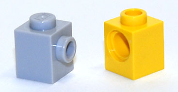
Some parts have knobs on their sides to allow the direction of building to be changed by a right angle:
Where are the knobs on the vertical faces? Look at the smallest one:
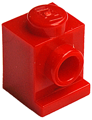
Put a 1×1 plate on it:
One expects the plate's sides to be flush with the brick's sides and top. Therefore the knob should be at half the plate height from the top: 7.8mm/2=3.9mm.
And then its centre is 5.7mm from the base of the brick.
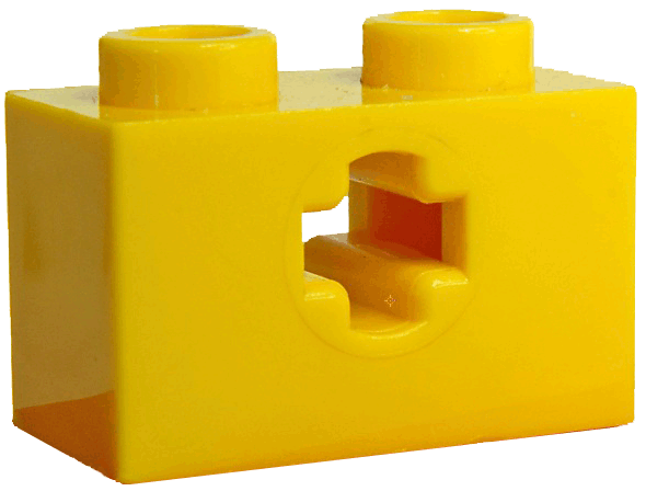
Axles and Bearings
Knobs do fit in the holes of axle bearings, albeit tightly.
The bearing hole diameter is 4.9mm, and the tightness of the grip on a knob can be explained by the fact that knobs normally are held only at a few points around their rim (usually three) whereas a bearing hole grips it along all points of its circumference.
Technics Bearing Height
This is arguably the most difficult to measure dimension: how high above the base is the centre of the bearing hole of a Technics brick?
Where would be a reasonable place?
Considering a bearing in a 1×1 brick, where would the centre "logically" go? Possibly at the centre of a square that fits either at the top or at the bottom of the rectangle that makes the front of the 1x1 brick:
But as bearing bricks have multiple bearing holes, and they must be 8mm apart, one could take a square of 8mm×8mm, the conceptual width of the brick, and set it at the top of the brick: the red square in dotted outline. Its centre is at 4mm from its top, hence at 5.6mm above the base. Or we could use the blue dotted line square, which sits at the bottom. In the first case the centre is 5.6mm above the base, in the second only 4.0mm.
It might even go in the middle between top and bottom, at 9.6mm/2=4.8mm.
Clearing knobs
An axle is 4.8mm in diameter. A bearing hole at 4.0mm would put the bottom of an axle of 4.8 at 4.0mm−4.8mm/2=1.6mm from the base, and thus the axle would not clear a knob of a brick in front of it.
At 5.6mm it clearly would.
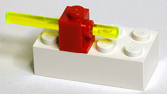
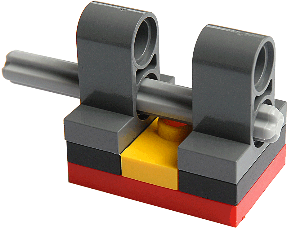
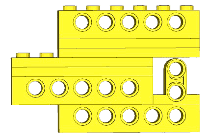
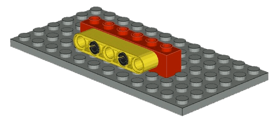
First look at this assembly, in which a special vertical bearing brick appears:
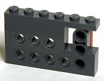
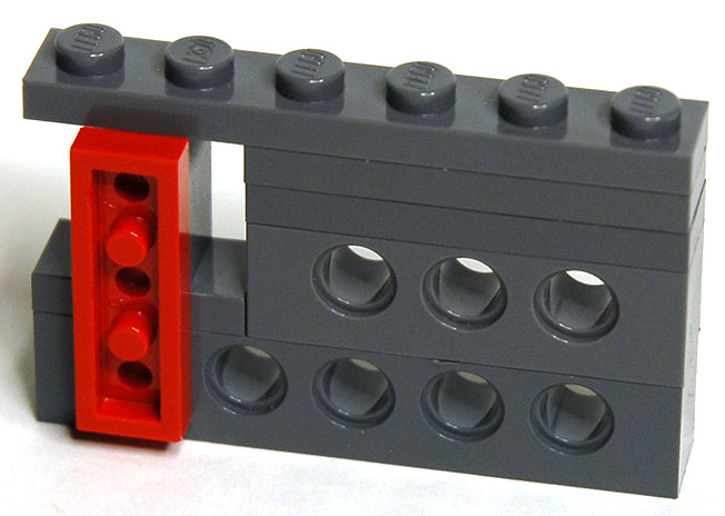
The special brick on top of a normal Technics bearing brick gives us a series of three holes in a vertical line with 8mm distances, so the vertical red plate fits exactly. But there is almost no clearance between the top of the special brick and the bottom of the plate above it.
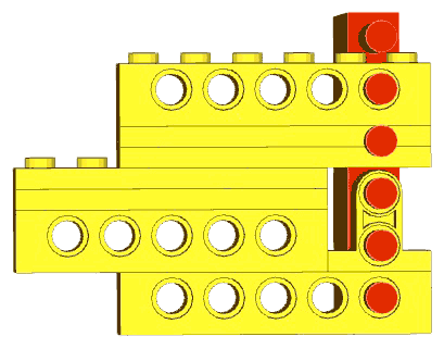
In the drawing below the special brick is coloured yellow. It is strange in the sense that its width is only 7.4mmm whereas other beams are 7.8mm wide. That does leave a gap of 0.1mm between its round top and the bottom of the plate covering it. Careful measurement gives:
from which I conclude that the technics axle holes are at 5.8mm from the bottom of the bearing bricks.
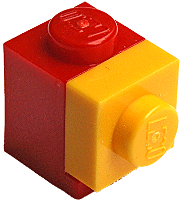
This is very slightly different from the height of the front knob on certain direction-changing bricks. Consider this assembly, in which a 1×1 brick with a knob on each of its vertical faces is used to hold three small plates:
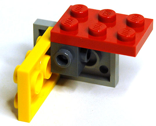
The knobs on the vertical faces must sit in the centre of a square of 7.8mm×7.8mm flush with the top, i.e. it is 7.8mm/2=3.9mm from the top and hence 9.6mm-3.9mm=5.7mm from the bottom, exactly (if I am right about the play of 0.1mm).
Is there really a difference of 0.1mm between the height of a Technics axle hole and a front knob? Yes. Make the following two assemblies, very carefully, and observe them closely; first:
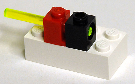
The last photo was very difficult to make, requiring careful alignment, but you can see that the axle hole is slightly higher than the rod. Secondly:
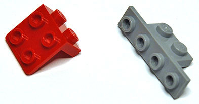
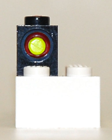
More evidence in favour of 5.8mm
The assembly is not exactly flush with the surface, the grey brick is lifted “off” by 0.1mm, which causes the combination to tilt slightly. Highly exagerated, what you see in the photo above is:
I am not adamant about the 5.8mm value, and that value is also not very important. If all axle holes were displaced vertically by a certain amount, all gears and wheels would still work in exactly the same way as they do now, because the distances between holes would not change.
I have not found a reason why the axle hole should be slightly higher, but both measures are also present in Lego’s own Lego Digital Designer program and you can use it to make a virtual copy of the front knob brick and the Technics bearing to observe the same difference.
Diameter of bearing holes
Axles are 4.8mm in diameter but they turn nicely in the bearing holes of Technics bricks. How big are these holes? It is difficult to measure them with calipers because the fingers have a certain thickness which causes a slight error when pressed against a concave surface. They do grip knobs very tightly, so they must be slightly smaller than the knob diameter. One way of measuring them is to insert two axles and measure at which distance they can be made to touch without forcing them:
This method is fraught with little problems: firstly one has to be sure the axles are very straight, which the longer ones are generally not; secondly one has to turn the axles so that the “cross” figure cross section lines up correctly otherwise the angles will be wrong; thirdly it is not easy to determine the length at which the axles are just touching but not forced together.
The internal length of an axle bearing hole is difficult to determine too because there is a recessed ledge at each side. It turns out to be 6.2mm. In the figure below the red trapezium and the dotted green rectangle indicate how to get the angle over which the axles are turned. I’m skipping the trigonometry here, but the diameter of the holes can be calculated from the angle of the axles, the distance at which they touch and the length of the hole.
The diameter of a bearing hole is close to 4.90mm
Flexibility
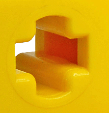
One way to ensure bricks will stick to each other with sufficient friction is to produce them with very high precision. This was certainly the case for early bricks. But recently there has been much more use of thinner walls and reproducible flexing. Look at the inside of the knobs on top of a recent Technics bearing brick:
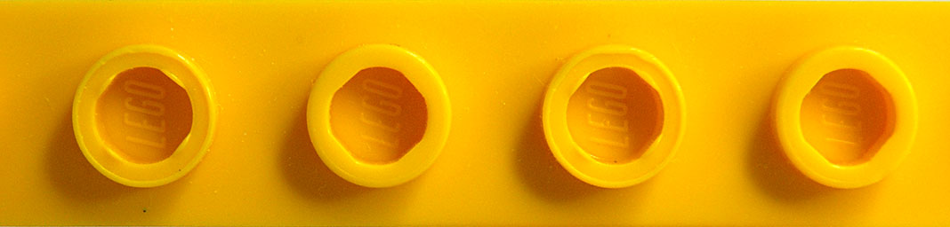
There are four bumps. These bumps will hold a rod reliably, without the necessity of high precision, because the walls of the knob will bend slightly and they are only pushed outward where those bumps are. A curious feature is that every other knob has a top surface with a depression; (for which I have no explanation). But now look at the knobs of an older part, a classic window:
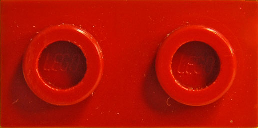
These are perfectly round inside and have much thicker walls: a rod cannot be inserted in the hole. Most knobs have a hollow on their other side, to save on plastic material. That hollow can be moulded easily in parts that are open on one side, but not in windows which have a sill, or in Technics bearing bricks where the bearing is in the way. For these the hollow is made from the top, and the hollow was different in the earlier days.
Conclusions
From all this I can only conclude that the fabrication process of Lego bricks is extremely precise: all bricks I have ever had do fit together almost equally well. It is really rare to find an element that fits significantly more loosely or more tightly than others. All axles turn very well in their bearing holes. And so on. The only aspect that I have not taken into account is the flexibility of the plastic. That plays a significant role too of course, but not in such circumstances as axles turning in bearings or the observation that knobs always fit more tightly in bearing holes than in other places, etc. I believe the molds are made to a tolerance smaller than 0.01mm (10µ, but some sources indicate it is closer to 5µ. For comparison, makers of quality watches use 2µ.
Not so approximate
There are some approximations out there. I examine two cases here.
LDraw
Without subtracting from the enormous work that went into the LDraw project and all the merits it has, the LDraw 3D models are approximations. I do not know the reasons for their choices. The LDraw organisation is a fantastic resource for Lego enthusiasts, and the following remarks do not aim to criticise their work; and their goals are different from mine.
On page http://www.ldraw.org/article/218 the LDraw Unit is defined. LDraw does not take the play gaps into account, but the LDraw group very wisely uses a unit that is connected to the bricks themselves, not to another unit. They also wisely choose the unit small enough that for all assemblies of bricks, distances can be measured in whole numbers of units (this obviously does not apply to curvy shapes such as animals and accessories for minifigs, but relative distances are not relevant there). The LDraw unit is 1/20th of a design knob distance, i.e. 0.4mm. A plate is then 8 units high (3.2mm), a standard 1×1 brick is 20×20×24 units (8.0mm×8.0mm×9.6mm). This makes the knob 12 units in diameter (4.8mm) and 4 units high (1.6mm).
However, the remark on real world approximations given on that page is wrong: at room temperature 1LDU is certainly exactly 0.4mm, and the value 1/64 inch is certainly wrong. The LDraw brick models will nevertheless work fine between themselves. They are approximations of the real bricks, as I argue below, and in the C4D models I make for myself I also use some approximations.
When looking at 3D models of bricks the obvious element for comparison is the height of the axle hole in the Technics bearing bricks. This is 5.8mm and the LDraw models use 5.6mm instead (as far as I could determine). That leads to small errors, but as stated above, shifting the bearing hole heights only displaces the linked elements but does not cause any strain anywhere because all holes are shifted by the same amount. Look at this assembly made with BrickSmith using LDraw bricks. It has Technics bearing bricks, plates, and one special brick with two holes arranged vertically:
There is a fair gap between the top of the special brick and the bottom of the plate sticking out over it, which does not occur in reality. That is simply because the holes in that special brick must be spaced 8mm vertically from the bearing brick hole, so they too must be 0.2mm lower, and therefore the gap is larger than in reality. Now stick a 1×6 plate vertically in those holes and you get:
In this construction I exaggerated the knob height of the plate by a factor of 6 so that the knobs would visibly stick through the bearing holes (and unfortunately also through the plates, but this is virtual stuff anyway). What you see is that everything fits nicely, because the hole in the top bearing beam is also 0.2mm too low down.
Examine another LDraw assembly, of a Technics beam connected to a Technics bearing brick:
The top of the yellow beam is slightly lower than the top of the red bearing brick, and the bottom of it clears the knobs on the plate. This is easier to observe in a frontal view:
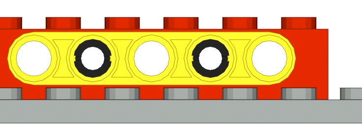
The reality is that the knobs are 1.8mm high (this is best measured on a Technics bearing brick, which does not have the word “lego” embossed on each knob) and not 1.6mm as in the LDraw models. But as the bearing holes are at 5.8mm from the bottom, not 5.6mm, in reality too the yellow beam clears the knobs, but its top is flush with the top of the bearing brick, which it fails to be in LDraw.
LDD
LDD is Lego’s own 3D program for building models. It has a wonderful function for making instructions for anything you build in it. Truly difficult to do, and great work. But some of its parts are wrong.
Look at this assembly of a 40 tooth gear meshing with a 24 tooth gear:
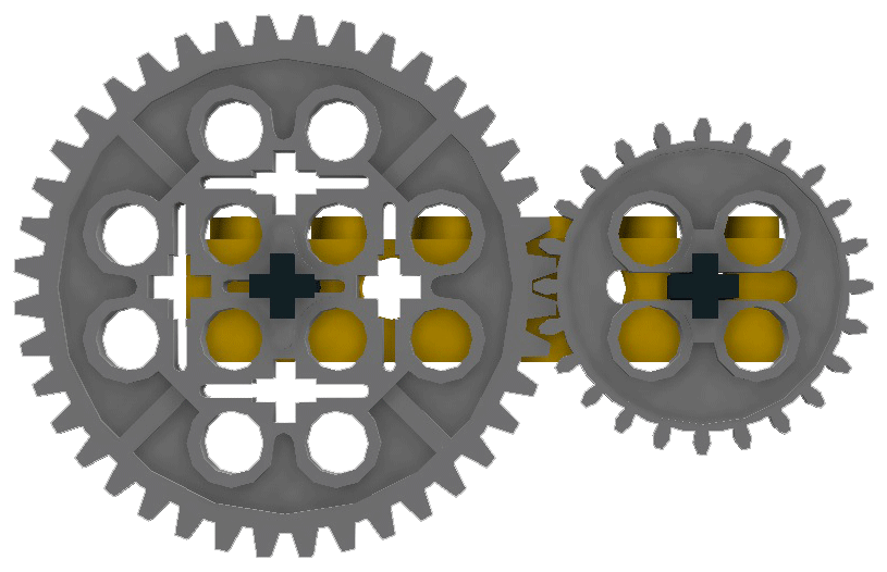
Both axles are exactly aligned (rotation angle 0º relative to the Technics bearing brick) and the two gears seem to mesh.
But that cannot be so. The teeth on the LDD model of the 40 tooth gear are not like on a real wheel, they are rotated relative to the wheel’s body by half a tooth! This is what real Lego 40 tooth wheels look like (though in the image they are also 3D models):
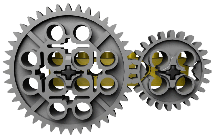
The axles are also aligned with zero rotation, showing that the teeth would not mesh but overlap. In real Lego the positions would have to be:
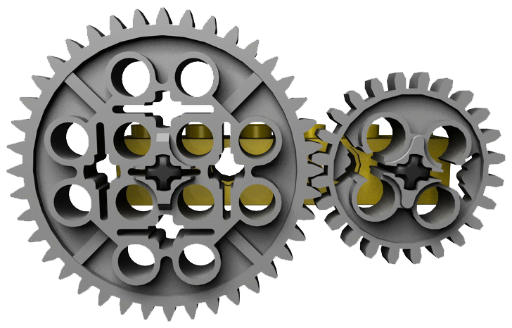
Now the teeth mesh properly, but the 24 tooth wheel has been rotated by half a tooth, i.e. over 360/24/2=7.5º
That is not much, but anything else fixed to the axles would therefore also be rotated and could not possibly line up if that were desired (but they can in LDD!). It does not matter which wheel combinations are used, nor how many intermediate wheels are inserted, there will always be some difference in the angles of the axles, and there are cases where this effect is very annoying. It does not occur in Meccano, where a wheel is fixed to a smooth axle by means of a small screw and the angle of any wheel relative to the axle can be determined at will. Lego’s wheels fit on their axles only in four rotational positions (in steps of 90º) because of the shape of the axles’ cross section.
Tradition, Tradition?
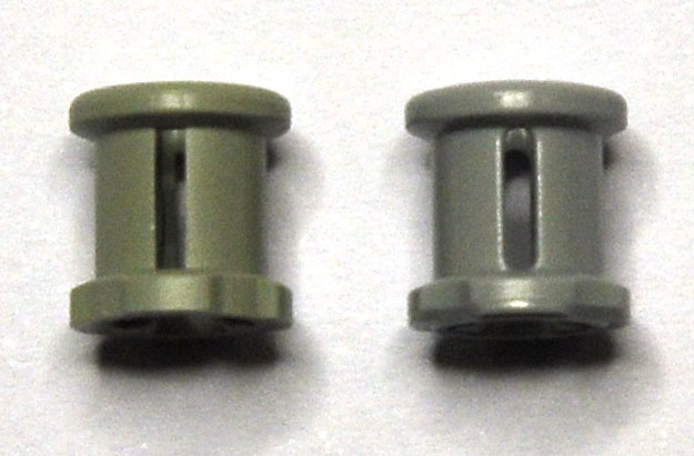
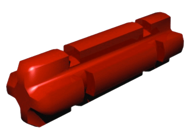
So, to have reasonable play, bricks of n knobs have a width of n×8-0.2mm. A one-knob brick is not 8.0 but 7.8 wide. Now when I wanted to measure the gears and bushings of Technics, I found it very difficult to get good figures. Until I saw that in fact there are two different versions of those parts: old ones and recent ones. The old bushing is 7.8mm high, the new one is 8.0mm.
The two can be distinguished by two visible features, but you have to look closely: one is that the ends of the new ones have slight ridges to add the extra 0.1mm on each end, the other is that the slots in the side are rounded instead of rectangular.
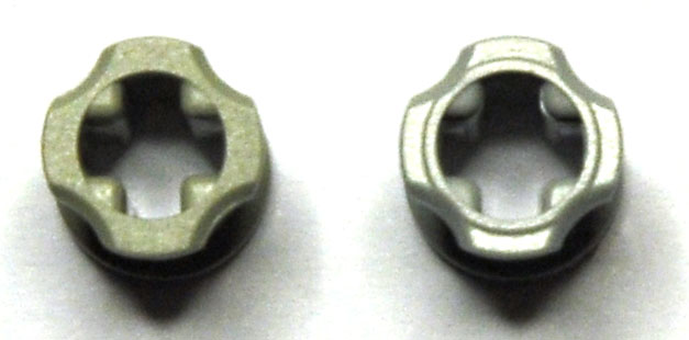
The rounding of the slots is a good idea. Any opening with sharp corners will crack under stress, which explains why slits in leather fittings will end in a round hole to stop the tearing at the end of the slit and why it is easy to break chocolate tablets along the sharp notches. The new bushings with rounded slots will not so easily crack. Indeed, I only ever had two broken Lego parts, and both were bushings: the sides split.
But what happened with the change from 7.8 to 8.0? I surmise that there was a mantra inside Lego: “dimension is n×8 minus 0.2mm”. Thus the person(s) who designed the Technics parts made the bushings and gear hubs 7.8mm high. Out of tradition?
But when you slide gears, wheels and bushings onto axles, you push them together since you have no guiding reference points on the axles. You therefore want them at exactly 8.0mm intervals, to match the Lego grid. Bushings are meant to hold things in place too, so you do not want the 0.2mm play.
Tradition helps doing repetitive tasks with efficiency, but it stands in the way of imagining solutions to new problems. The production dimensions of parts that slide onto axles should firmly be 8.0mm. Someone realised this later on, and the newer parts are 8.0mm.
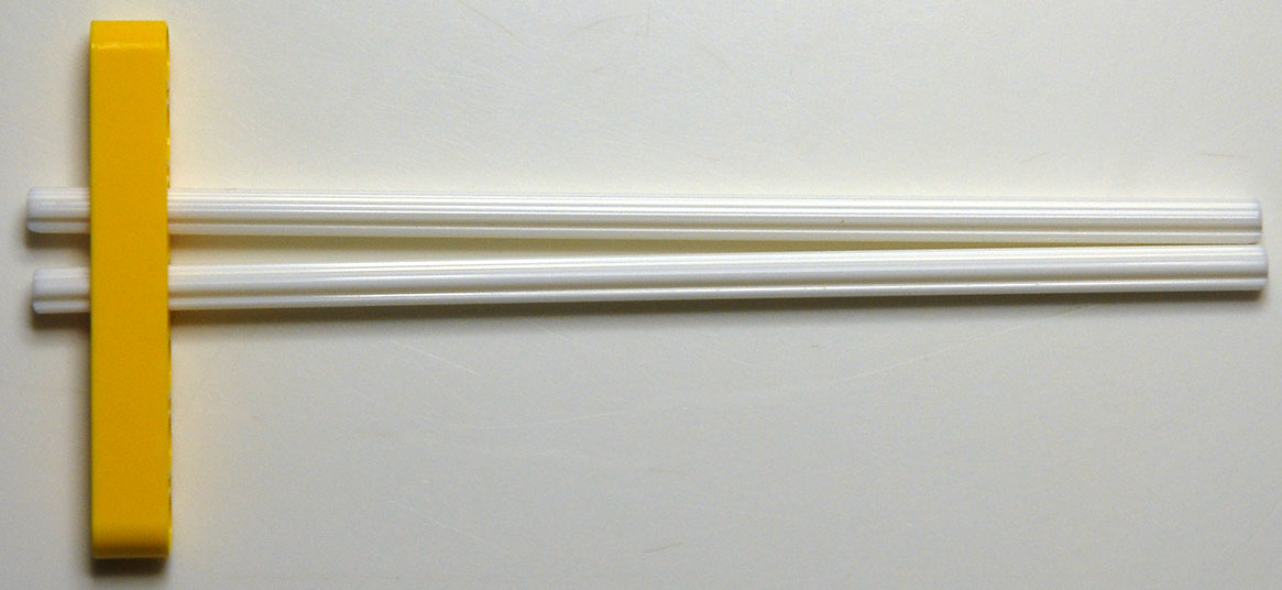
If you do not believe this, examine:
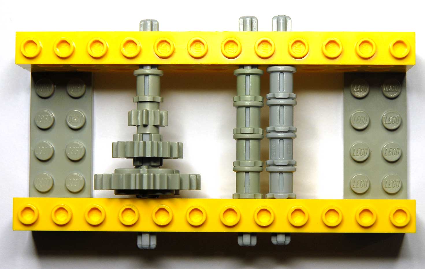
The axle on the left has four old parts on it: a bushing, an 8-gear, a 16-gear and a 24-gear; it leaves a large gap between the top element and the yellow bearing brick. The second axle has four old bushings and also leaves a large gap, while the last axle has four new bushings and only has the 0.2mm gap that is necessary (derived from the fact that the distance between the faces of the bearing bricks themselves is 4×8+0.2mm)
The difference between the rectangular slots and the rounded slots in the bushings is also again visible.
If you examine Technics connectors closely you will see that many of them have at least one side that slides on an axle, and that side should be 8.0mm high.
Axle gripping
Gears, bushings and connectors grip axles with a fair amount of friction. Some of these parts have small internal “bumps” to provide this friction reliably. They are barely visible:
A close-up:
|

|
These bumps can be felt when inserting one of the newer type length 2 axles like this one:
The bumps are also very “old” in the sense that even early connectors have them.